The Biggest Causes of Failed Fibre Installations
A fibre installation that fails does not usually fail because the technology is difficult. It fails because one or more of a small number of well-understood problems was not addressed before, during or after the installation.
Fibre optic cabling has become the default choice for backbone links, long horizontal runs and increasingly for end-to-end connectivity in residential, commercial and broadband deployments. The technology is mature, the products are well-developed, and the standards that govern performance are clear. Yet failed installations remain a common and costly problem across the industry - costly in engineer time, in repeat visits, in project delays and, in occupied buildings, in disruption to the people living or working there.
Most failures are preventable. They fall into a recognisable set of categories, and understanding those categories is the starting point for eliminating them.
Contamination at the Connector
Contamination is the single most common cause of fibre link failure, and it is also the most preventable. A fibre optic connector has a core diameter of between 9 and 62.5 microns depending on the fibre type. A particle of dust or a fingerprint on the end face of a connector does not need to be large to cause a significant insertion loss problem - it needs only to be in the path of the light.
The consequences of contaminated connectors range from elevated insertion loss on an otherwise compliant link through to complete failure to pass light. In an installed system, contamination can also cause physical damage. A contaminated connector mated with a clean one transfers the contamination, and if a particle is trapped between the two end faces under the mating force of the connector, the result can be a scratched or cracked fibre end face that cannot be repaired without re-termination.
The solution is straightforward: inspect every connector before mating, clean any connector that does not pass inspection, and inspect again. A fibre inspection probe or video microscope is not optional equipment for a professional fibre installation - it is a standard part of the toolkit. The IEC 61300-3-35 standard sets out the inspection criteria. Engineers who follow the clean-before-mate discipline consistently will eliminate the majority of contamination-related failures before they happen.
Poor Termination Technique
The quality of a fibre termination determines the insertion loss and return loss at that connector. Both parameters are tested as part of a compliant installation, and both are directly affected by the technique used to terminate the fibre.
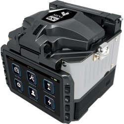
For field-terminated connectors, the cleave quality is critical. A fibre cleaver that is worn, incorrectly set or being used without proper training will produce end faces that are angled, chipped or rough. These defects generate elevated insertion loss and back-reflection figures that may sit just inside the limit on a warm day and outside it when the temperature drops and the physical geometry changes slightly. A high-quality cleaver, maintained and used correctly, produces consistent perpendicular end faces that mate cleanly and perform reliably. Field terminations are not current thinking and many will fail the end face inspection limit.
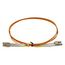
Pre-terminated assemblies remove the field termination variable entirely, provided they are sourced from a manufacturer with rigorous production testing on every connector. For installations where consistency and speed are critical, pre-term is often the lower-risk option but only if the assemblies are handled correctly on site.
Bend Radius Violations
Fibre does not behave like copper when it is bent beyond its minimum bend radius. Copper cable that is bent too tightly may fail a return loss limit. Fibre cable that is bent too tightly loses light - sometimes a little, sometimes a lot, depending on how tight the bend is and how long the fibre stays under that stress.
Bend radius violations happen in several predictable places. Cable pulled through conduit or trunking with a tight corner at the entry point. Cable looped inside a cabinet or enclosure to take up slack, with the loop diameter determined by available space rather than the cable's minimum bend radius. Patch leads dressed into a cabinet and pushed against the back or side wall. Drop cables in residential installations pulled over a corner without a protective radius former.
In many cases, the violation is invisible once the installation is complete. The cable looks fine. The test results on the day of installation are acceptable, because the fibre is under tension and the bend geometry is slightly different under load than it will be at rest. Six months later, when the installation has settled, the link is marginal or failing.
The minimum bend radius figures for the cable types being used should be understood and observed at every stage of the installation - during pulling, during routing and during final dressing. Where the physical environment makes this difficult, the right solution is a product designed for the application, not a standard cable forced into a geometry it was not designed for.
Incorrect Cable Selection for the Environment
Not all fibre cable is suitable for all environments. The distinction between indoor and outdoor rated cables, between loose tube and tight buffered constructions, between armoured and unarmoured, and between CPR fire ratings, jacket materials exists for good reasons. Using the wrong cable type for the environment it is being installed into creates problems that may not surface during installation or initial testing, but will emerge over time as the installation is exposed to the conditions it was not designed for.
External cables installed internally without the appropriate transition or re-entry housing present a fire classification issue. Indoor cables installed externally, even under cover, absorb moisture over time and the jacket degrades. Direct burial cables installed without the specified bedding and cover depth are vulnerable to mechanical damage. Tight buffered cables installed in duct systems designed for loose tube may not pull cleanly over the required distances.
The specification stage is the point at which these decisions should be made, with the installation environment fully understood. Where the specification is inherited or ambiguous, it is worth verifying the cable type against the actual conditions before ordering material and before beginning work.
Testing Errors and Incorrect Reference Methods
A fibre installation that has been correctly installed and correctly terminated can still produce a failing test result if the test is set up incorrectly. Reference method selection, launch lead condition, test direction and equipment calibration all affect the result, and errors in any of these produce figures that do not represent the true performance of the link.
The three reference methods defined in ISO/IEC 14763-3 produce different insertion loss results for the same physical link, because they account for the connector losses at the launch and receive ends differently. Using the wrong reference method for the type of installation being tested, or mixing reference methods across a project, creates results that are not comparable and may not be compliant even if the physical installation is sound.
Launch and tail leads must be in good condition and must be inspected and cleaned before use. A launch lead with a contaminated or damaged connector introduces a loss that is attributed to the link under test. Damaged launch leads are a persistent problem on sites where the test equipment is shared, used frequently and not maintained with the same care as the installation itself.
Equipment calibration and source power levels should be verified at the start of each day of testing. Results recorded with out-of-calibration equipment are results that cannot be relied upon, regardless of whether they show pass or fail.
Mechanical Damage During Installation
Fibre cable is not fragile, but it has specific mechanical limits that differ from copper. Maximum tensile load during installation, minimum bend radius under tension, and crush resistance are all parameters that need to be understood and respected during the pull.
Cable blown through microduct has different installation requirements from cable pulled through conduit. Pre-terminated assemblies have specific pull-through limits because the connectors and the termination points are the weakest elements in the assembly. Armoured cable provides physical protection after installation but does not remove the need to manage pulling tension during the installation process.
On busy construction sites, where multiple trades are working in the same spaces, fibre cable that has been installed but not yet protected is vulnerable to accidental damage. A cable run across a floor waiting for trunking to be fitted, or a patch cord routed through a cabinet before the equipment has been installed, can be stepped on, pinched or kinked without any visible external sign of damage. The fault shows up on test, or worse, intermittently in service.
Protecting installed cable during the construction phase, and carrying out a full test programme after all other trades have completed their work in the relevant areas, eliminates the risk of undetected mechanical damage being signed off as a compliant installation.
The Role of Training and Standards Knowledge
Running through all of the above is a common thread: most fibre installation failures are the result of technique, knowledge or process — not the technology itself. An engineer who understands fibre inspection standards, knows the correct termination process for the products being used, understands bend radius requirements and can set up a test correctly will deliver a consistently passing installation. One who does not will encounter failures that are difficult to diagnose, expensive to rectify and damaging to the project programme.
Formal training in fibre optic installation and testing is not a bureaucratic requirement. It is the most reliable way to transfer the knowledge and technique that separates a first-time pass from a return visit.
Connectix runs fibre optic training courses covering installation, termination and testing at our Braintree facility, with practical hands-on sessions using the equipment and products used on live projects. The Connectix Approved Installer Programme provides the framework for ensuring that installations carried out using Connectix products are completed by engineers with the training and knowledge to deliver a certified, warranted result.
If you would like to discuss training, product specifications or support on a current project, get in touch with the Connectix technical team.
📞 01376 346600 📨 sales@connectix.co.uk